(Originally posted 2014-04-01.)
There’s been some interest recently in whether a zBC12 as a standalone Coupling Facility would be a good idea. Having replied to one such question in email form I can count that as a draft for a blog post on the subject. It’s a complex question as are most about Parallel Sysplex configuration design. So this won’t be a comprehensive answer but I hope it’ll give you food for thought and perhaps a new way of looking at the relevant performance data.
There are two main themes worth exploring:
- What a stand-alone zBC12 allows you to do
- Signalling sensitivity to technology options
The second of these is a particularly boundless discussion. So let’s get started: I have a kettle to boil that ocean in. 🙂
A Stand Alone Coupling Facility
Consider the case of a twin-ICF[1] Parallel Sysplex environment where all the members are on the same pair of physical machines as the two ICFs.[2]
There are two design choices:
1) Duplexing [3] key structures across the two ICFs,
2) Not duplexing the structures.
The first choice is, thankfully, far more common than the second. It enables far higher availability and much greater resilience.
Consider the oft-cited case of a 2-way DB2 Data Sharing[4] Group where the LOCK1 structure is unduplexed and on the same footprint as one of the members[5]. Suppose this footprint suffers a hardware failure: Both the LOCK1 and one of the members fails and you’re in for a painful wait while the entire Data Sharing group restarts.
Here’s what a duplexing scheme looks like. It’s symmetrical. Often the two machines are in separate machine rooms some distance apart, but sometimes they’re sat next to each other.[6]
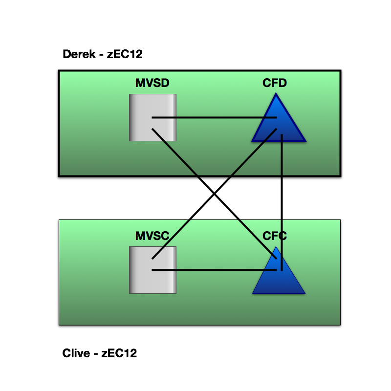
If instead you place the vital structures in a standalone zBC12 you would need both the zBC12 and one of the coupled machines to fail to cause the same group-wide restart.
Here’s what a standalone configuration could look like:

I’ve drawn the zBC12 (“Bairn”) nearer to “Derek” as in practice I don’t tend to see a third data center just to house the standalone CF. “Nearer” usually means shorter request response times, so we no longer have symmetry of outcomes between the two coupled members. This might matter.
There are, of course, other similar designs. One of these is a third footprint’s ICF where the other LPARs on that third footprint are in a totally separate parallel sysplex. To talk about these possibilities further would unnecessarily complicate an already long blog post.
One disadvantage of a stand-alone CF is that all the links between the coupled z/OS LPARs and the coupling facility are external, though this need not be an overwhelming disadvantage.
The rest of this post addresses how moving from a pair of ICFs affects performance.
Signalling Sensitivity
The key question is whether high-volume structures have good performance from the point of view of the coupled applications.[7]
When I examine a Parallel Sysplex environment I like to see data from all the members.[8]
To answer the question “would a slower-engined zBC12 suffice?” it’s necessary to understand what part CF engine speed plays in signalling and what the traffic is.
For a long time now RMF has reported Structure Execution Time (or, informally, structure CPU Time).[9] Assuming requests from one member to a structure take the same amount of CF processing as another we can estimate non-CPU time:[10]
If you subtract the CF CPU time for a request from the response time as seen by the member you get a reasonable view of the time used by queuing and signalling. You can’t really break these two out but they do between them represent the time not represented by the CF engine.
As an example consider the following case of a lock structure (DSNDB2P_LOCK1) in CF1 accessed by a member (SYSB) over a mixture of 4 Infiniband links and 1 ISC link[11]. All the requests are synchronous.
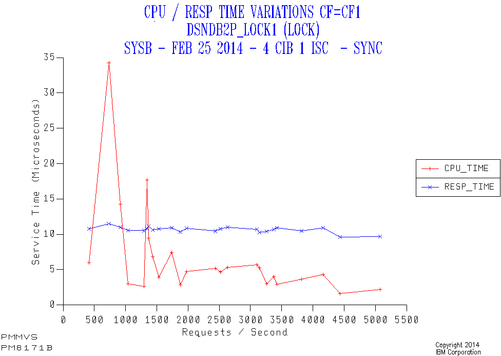
Along the horizontal axis is the request rate from the member to the structure. The red line is the CF CPU time per request, the blue being the response time.
- While the CPU time per request appears high at low traffic this is really an amortisation effect as there is a certain amount of cost for no traffic. I see this quite often.
- The response time stays constant – which is a good thing.
- Generally there’s quite a bit of a difference between the CPU time for a request and the overall response time. So the sensitivity to CF engine speed is not great. In this case the need to use external signalling links is what drives the difference – as the CF Utilisation is very low.
Obviously if the CPU time dominates then a slower processor (such as moving from a zEC12 ICF engine to a zBC12 one) risks delaying requests. Equally if the non-CPU time dominates the zBC12 engine speed isn’t likely to matter much.
In any case moving from a z196 ICF engine to a zBC12 ICF engine isn’t such a drastic drop in speed. A fortiori moving from z10.
I could stop there. But really the discussion should continue with the effects of removing duplexing, request CPU heaviness, queuing and signalling technologies. The queuing aspect might be unimportant but the other three certainly aren’t. But let’s deal with them all – at least briefly.
Queuing
Coupling facilities behave like any other kind of processor from the point of view of CPU Queuing, except their performance is more badly effected when queuing occurs.
For this reason (and for white space reasons) we consider CFs to be full at a much lower utilisation than z/OS LPARs. Multiprocessor CF LPARs are also preferred over single processor ones.
A zBC12 CF would have more processors than the equivalent capacity zEC12. It could offer a better queuing regime within the same capacity.
Removing duplexing
As you probably know there are two types of structure duplexing:
- System-Managed
- User-Managed
A good DB2 example of the former would be LOCK1 and the only IBM example of the latter DB2 Group Buffer Pools.
With System-Managed Duplexing every request is duplexed and the request must be completed in both CFs before z/OS sees the request as complete.
With User-Managed Duplexing only the writes are duplexed, which is generally a small subset of the requests to the Primary. But the requests that are duplexed must again complete in both CFs.
Each duplexed request takes at least the time of the slower of the two requests, so duplexing causes a variable amount of delay.
The greater the distance between the two CFs the greater the request elongation, of course.
So a standalone zBC12 could allow you to avoid this elongation and perhaps to design a configuration with machines further apart.
SIgnalling Technology And Distance
Consider the following example from the same customer as the first graph.
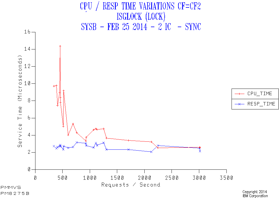
This is another lock structure (GRS Star instead of a DB2 LOCK1 structure). This time it’s in a different coupling facility (CF2) accessed through Internal Coupling (IC) links from the same member (SYSB).
Again all the requests are synchronous. But this time the response time is about 3 microseconds rather than the 10 for the first case. While the responsiveness to applications might not be very different there is an important effect:
Because all the requests are synchronous every request results in a coupled z/OS engine spinning for the entire duration of the request. For this reason the difference between 3 and 10 microseconds might well matter.
Obviously the further the distance and the slower the link technology the bigger the impact on request response times and, potentially the coupled CPU time.
Request CPU Heaviness
The two Lock Structure examples above had about the same CF CPU heaviness – 3 microseconds per request.
Consider the following case. It’s a DB2 Group Buffer Pool structure.

Here the CF CPU per request is variable but in the region of 15 to 20 microseconds, far heavier than for the two lock structures. As this structure is accessed from SYSB using IC links the CF CPU time dominates. So a slower CF engine would lead to longer request response times – under cirumstances like these where there is little CPU queuing in the CF.
(Notice how the Synchronous %[12] varies between 90% and 100% across the range of request rates. This could be a different mix of request types – as is entirely feasible with cache structures – or it could be the Dynamic Request Conversion heuristic converting some from Synchronous to Asynchronous as the response time increases. I prefer the former explanation here, but I’m not sure and no instrumentation will tell me.)
Conclusion
As always “it depends”. I’ve tried to give you a glimpse of on what and how it depends.[13] But usually I would expect a zBC12 stand alone coupling facility to be fine.
I appreciate that, if you’ve got this far, it’s been a very long read. Along the way you’ll’ve seen three graphs that each of them slightly “misbehave”: I consider the complexity and misbehaviour part of the deal when discussing Parallel Sysplex configuration and performance: It’d be hard to boil it down without missing something important.
-
Integrated Coupling Facility ↩
-
This is a particular common and generally good design. The discussion here extends neatly to other configurations WLOG[15]. ↩
-
For some recentish thoughts on Duplexing start with Coupling Facility Duplexing Reporting Warm-Over ↩
-
I prefer the spelling “Data Sharing” to the more-frequently-observed “Datasharing” but I’m not consistent in this. ↩
-
I see many two-member Data Sharing groups and about the same number of four-member Data Sharing groups. ↩
-
Usually I can tell the difference between the two cases, just from signalling times. ↩
-
Many structures have little traffic to them and their response times are rather less important. ↩
-
Some of the analysis relies on data for all the systems being collected. ↩
-
R744SETM is the field in the SMF 74–4 record. This appears on the RMF Coupling Facility Activity report. ↩
-
This isn’t an outrageous assumption but it isn’t 100% valid: For the case where the members are balanced and similar the traffic will be similar from each member – but async-vs-sync and operations like Castout processing could affect this. I suspect if one member is, say, doing completely different DB2 work to another the requests might be lighter or heavier. But I can’t prove this. ↩
-
We don’t know how much traffic goes over each link or even link type. ↩
-
The other two graphs don’t have this line. Instead they have the word “sync” in the title as all the requests are synchronous always. If the structure had been 100% Async (for example a XCF Signalling list structure) I’d’ve again suppressed the line and replaced it with “async” in the title. ↩
-
It’s the duty of anyone who says “it depends” to say on what and how – at least until the audience’s snoring gets too loud. 🙂 ↩

One thought on “zBC12 As A Standalone Coupling Facility?”