(Originally posted 2019-08-02.)
(I’m indebted to Howard Hess for the title. You’ll see why it’s appropriate in a bit.)
Since I wrote Engineering – Part Two – Non-Integer Weights Are A Thing I’ve been on holiday and, refreshed, I’ve set to work on supporting the SMF 99 Subtype 14 record.
Working with this data is part of the original long-term plan for the “Engine-ering” project.
Recall (or, perhaps, note) the idea was to take CPU analysis down to the individual processor level. And this, it was hoped, would provide additional insights.[1]
Everything I’ve talked about so far – in any medium – has been based on one of two record types:
- SMF 70 Subtype 1 – for engine-level CPU busy numbers, as well as Polarisation and individual weights.
- SMF 113 Subtype 1 – for cache performance.
SMF 99 Subtype 14 provides information on home locations for an LPAR’s logical processors. It’s important to note that a logical processor can be dispatched on a different physical processor from its home processor, especially probably in the case of a Vertical Low (VL)[2]. I will refer to such things as where a logical processor’s home address is as “processor topology”.
It should be noted that SMF 99–14 is a cheap-to-collect, physically small record. One is cut every 5 minutes for each LPAR it’s enabled on.
Immediate Focus
Over the past two years a number of the “hot” situations my team has been involved in have involved customers reconfiguring their machines or LPARs in some ways. For example:
- Adding physical capacity
- Shifting weights between LPARs
- Varying logical processors on and off
- Having different LPARs have the dominant load at different times of day
All of these are entirely legitimate things to do but they stand to cause changes in the home chips (or cores) of logical processors.
The first step with 99–14 has been to explore ways of depicting the changing (or, for that matter, unchanging) processor topology.
I’ll admit I’m very much in “the babble phase”[3] with this, experimenting with the data and depictions.
So, here’s the first case where I’ve been able to detect changing topology.
Consider the following graph, which is very much zoomed in from 2 days of data – to just over an hour’s worth.
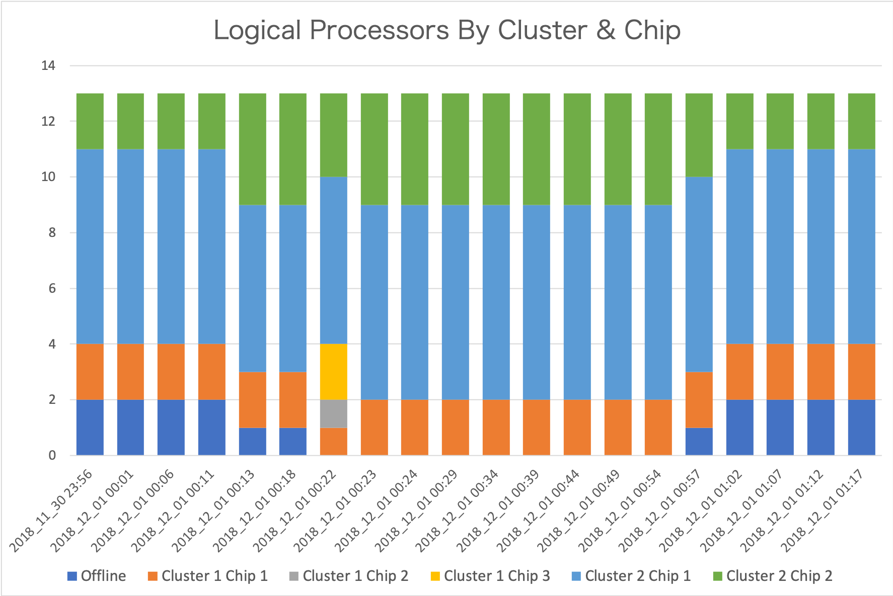
Each data point is from a separate record. From the timestamps you can see the interval is indeed 5 minutes. This is not the only set of intervals where change happens. But it’s the most active one.
There are 13 logical processors defined for this LPAR. All logical processors are in Drawer 2 (so I’ve elided “Drawer” for simplicity.)
Let me talk you through what I see.[4]
- Initially two logical processors are offline. (These are in dark blue.) Cluster 2 Chip 1 has 7 logical processors and Cluster 2 Chip 2 has 2.
- A change happens in the fifth interval. One logical processor is brought online. Now Cluster 2 Chip 1 has 6 and Cluster 2 Chip 2 has 4. Bringing one online is not enough to explain why Cluster 2 Chip 2 gained two, so one must’ve moved from Cluster 2 Chip 1.
- In interval 7 another logical processor is brought online. The changes this time are more complex:
- A logical processor is taken away from Cluster 1 Chip 1.
- A logical processor appears on Cluster 1 Chip 2.
- Two appear on Cluster 1 Chip 3.
- One is taken away from Cluster 2 Chip 2.
- Towards the end, as each of two logical processors are offlined they are taken away from Cluster 2 Chip 2.
The graph is quite a nice way of summarising the changes that have occurred, but it is insufficient.
It doesn’t tell me which logical processors moved.
What we know – not least from SMF 70–1 – is the LPAR’s processors are defined as:
- 0 – 8 General Purpose Processors (GCPs)
- 9 – 12 zIIPs
The Initial State
With 99–14, diagrams such as the following become possible:
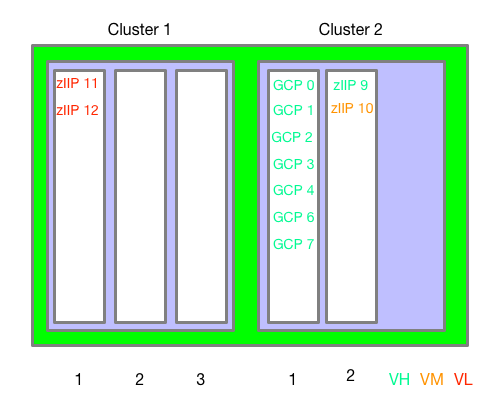
This is the “original” chip assignment – for the first 4 intervals.
This is very similar to what the original WLM Topology Report Tool[5] would give you. (I claim no originality.)
I drew this diagram by hand; I can’t believe it would be that difficult for me to automate – so I probably will.[6]
After 1 Set Of Moves
Now let’s see what it looks like in Interval 5 – when a GCP was brought online:

GCP 5 has been brought online in Cluster 2 Chip 2, alongside the 2 (non-VL) zIIPs. But also GCP 0 has moved from Cluster 2 Chip 2 to Cluster 2 Chip 1.
What’s The Damage?[7]
Now, what is the interest here? I see two things worth noting:
- A processor brought online has empty Level 1 and Level 2 caches.
- A processor that has actually moved also has empty Level 1 and Level 2 caches.
Within the same node/cluster or drawer probably isn’t too bad. (And within a chip – which we can’t see – even less bad as it’s the same Level 3 cache). Further afield is worse.
Of course the effects are transitory – except in the case of VLs being dispatched all over the place all the time. Hence the desire to keep them parked – with no work running on them.
After The Second Set Of Moves
Finally, let’s look at what happened when the second offline GCP was brought online – in Interval 7:
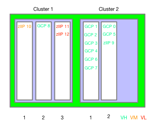
GCP 8 has been brought online in Cluster 1 Chip 2. But also zIIP 10 has moved from Cluster 2 Chip 2 to Cluster 1 Chip 1. Also zIIPs 11 and 12 have moved from Cluster 1 Chip 1 to Cluster 1 Chip 3.
This information alone (99–14) isn’t enough to tell you if there was any impact from these moves. However, you can see that in neither case was a “simple” varying a GCP online quite so simple. Both led to other logical cores moving. This might be news to you; It certainly is to me – though the possibility was always in the back of my mind.
Note: This isn’t a “war story” but rather using old customer data for testing and research. So there is no “oh dear” here.
Later On
To really understand how a machine is laid out and operating you need to consolidate the view across all the LPARs. This requires collecting SMF 99–14 from them all. This, in fact, is a motivator for collecting data from even the least interesting LPAR. (If its CPU usage is small you might not generally bother.)
But there’s a snag: Unlike SMF 70–1, the machine’s plant and serial number isn’t present in the SMF 99–14 record. So to form a machine-level view I have two choices:
- Input into the REXX exec a list of machines and their SMFIDs.
- Have code generate a list of machines and their SMFIDs.
I’ll probably do the former first, then the latter.
What also needs doing is figuring out how to display multiple LPARs in a sensible way. There is already a tool doing that. My point in replicating it would be to add animation – so when logical processors’ home chips change we can see that.
Maybe Never
SMF 99–14 records aren’t cut for non-z/OS LPARs, which is a significant limitation. So I can’t see a complete description of a machine. For that you probably need an LPAR dump which isn’t going to happen on a 5-minute interval.
However, for many customer machines, IFL- and ICF-using LPARs are on separate drawers. It’s a design aim for recent machines but isn’t always possible. For example, a single-drawer machine with IFLs and GCPs and zIIPs will see non-z/OS LPARs sharing the drawer. Most notably, this is what a z14 ZR1 is.
One other ambition I have is to drive down to the physical core level. On z14, for instance, the chip has 10 physical cores, though not all are customer-characterisable. But this won’t be possible unless the 99–14 is extended to include this information. This would be useful for the understanding of Level 1 and Level 2 cache behaviour.
Finally, there is no memory information in 99–14. I would dearly love some, of course.
Conclusion
While 99–14 doesn’t completely describe a machine, it does extend our understanding of its behaviour by relating z/OS logical processors to their home chips. Taken with 70–1 and 113–1, this is a rather nice set of information.
Which prompts lots of unanswerable questions. But isn’t that always the way? 🙂
A question you might have asked yourself is “do I need to know this much about my machine?” Generally the answer is probably “no”. But if you are troubleshooting performance or going deep on LPAR design you might well need to. Which is why people like myself (and the various other performance experts) might well be involved anyway. So – for us – the answer is “yes”.
The other time you might want to see this data “in action” is if you are wondering about the impact of reconfigurations – as the customer whose data I’ve shown ought to be. 99–14 won’t tell you about the impact but it might illuminate the other data (70–1 and 113). And together they enhance the story no end.
-
Actually it’s a matter of “legitimised curiosity”. 🙂 ↩
-
I’ll follow the usual convention of “VL” for “Vertical Low”, “VM” for “Vertical Medium ”, and “VH” for “Vertical High”. ↩
-
See, perhaps, Exiting The Babble Phase?. ↩
-
You might well see something different. And that’s where the fun begins. ↩
-
Which I now can’t find. 😦 and couldn’t run even if I could find it. ↩
-
Actually, I’ve experimented with creating such diagrams using nested HTML tables. It works fine. The idea would be to write some code (probably Python) to generate such (fiddly) HTML from the data. ↩
-
In UK English, at least, “What’s the damage” means “what’s the bill”. ↩

Yourr the best
LikeLike